The fundamental concept of the keyless coupling is to create a large frictional grip between the coupling and the shaft by “shrinking” the coupling ID, thus creating an interference fit with the shaft. As the coupling is installed, the hub OD expands, and measurement of this expansion gives the installer accurate knowledge of the pressure at each shaft end. This results in accurate, repeatable, and reliable performance.

Design Features
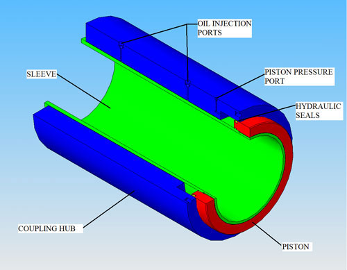
The components are forged and machined high-strength steel, although corrosion resistant materials can be used for underwater applications. The bore of the sleeve is machined to an F7 or E7 tolerance and has spiral grooves which ensure that oil on the shaft surface can escape as the coupling squeezes down. The shaft ends are machined to an h7 tolerance. The hub has two ports for injecting oil between the hub and sleeve during the installation process. A system of interconnected grooves on the hub ID ensure that the oil is uniformly distributed, greatly reducing friction and allowing the surfaces to glide without galling. Slightly recessed grooves on the hub OD are positioned for measurement of hub expansion over each shaft end.
Mapeco couplings are available in both straight and flanged configurations, and can be designed to meet the requirements of almost any shipboard application.
Mapeco keyless couplings offer the following advantages over conventional removable keyed couplings:
- Elimination of keyway means no stress concentrations, permitting smaller shaft diameter
- Couplings require only straight machining of shaft ends
- Shaft ends can be rotated at any angle to help eliminate resonance vibration problems between the engine and propeller
- Couplings are interchangeable between shafts
- Frictional grip provides a completely rigid connection under all conditions, enhancing reliability
- Installation and removal is quick and simple; no heating is required

Straight Couplings
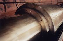
Straight couplings are used where the ends of the two shafts are straight. Common locations include between outboard shafts, inside stern tubes, and between line shafts. Couplings in outboard locations can be made from corrosion resistant materials such as stainless steel or Monel or they can be provided with watertight covers. Couplings located in inboard locations are normally made from steel without covers. There is some flexibility in the design to use couplings that are longer and thinner or shorter and wider depending on the available space.
Flanged Couplings
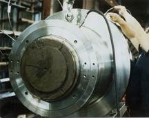
Flanged couplings are most often used to connect line shafts to reduction gear or drive motor shafts. The coupling can include an integral brake flange or a separate brake flange can be bolted to the coupling flange. The flange size can be adjusted to suit the flange on the reduction gear motor shaft. Mapeco has developed unique mounting configurations for connecting to smaller diameter shaft flanges.

Mounting and Dismounting
After the coupling is positioned on the shaft(s), the hub is easily driven up the taper on the inner sleeve utilizing the oil injection method. After the hub reaches its final position, the expansion of the hub is measured to ensure that the required grip on the shaft has been achieved and that the stresses in the coupling and shaft components are below their allowable limits. The coupling is now fully installed and ready for use.
To dismount the coupling, the oil injection method is once again used to expand the hub. The hub will slide down the taper on the inner sleeve when the oil pressure is released from the piston cavity. The coupling can then be removed from the shaft.

